
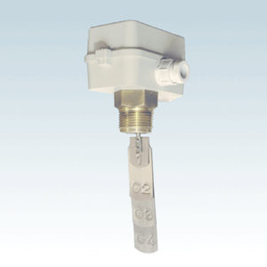
“FC83” FLOW SWITCHES
A flexible blade, stimulated by the flow, acts on the control lever of a microswitch in SPDT switching. The electric connection may be prepared for the control of pumps, burners, compressors, alarm signals and motor driven valves. They are mounted on sections of horizontal pipes, far from valves, elbows, discharges or irregular flows.
COMPLIES WITH CEI EN 60947-5-1 STANDARDS
CHARACTERISTICS
| NOMINAL INSULATION VOLTAGE | Ui 380V |
| NOMINAL CONTINUOUS CURRENT | 10A |
| NOMINAL EMPLOYMENT CURRENT LE | 220V – 250V~ |
| RESISTIVE LOAD | AC-12 – 16A |
| INDUCTIVE LOAD | AC-15 – 6A |
| DIRECT CURRENT | DC-13 0,2A |
TECHNICAL DRAWING/DETAIL


ACCESORIES
- Antishock thermoplastic material enclosure
- Paddles in inox AISI 301 for pipes from G1 to G8
- G1″ connection
- Female 6.3mm electrical connection
- Sealed cable gland Pg16
- Ambient temperature 50°C
| PIPELINE DIAMETER | PADDLE | Minimum flow rate (m3/h) value | Minimum flow rate (m3/h) value | Maximum flow rate value | Temperature °C | Degree of protection | |||
| decreasing | increasing | decreasing | increasing | ||||||
| G1 | 35 | 1 | 0,5 | 2 | 1,9 | 10 | -20 ÷ 110 | IP54 | |
| G2 1/4 | 35 | 1,2 | 0,7 | 2,9 | 2,7 | 10 | -20 ÷ 110 | IP54 | |
| G1 1/2 | 58 | 1,6 | 1 | 3,9 | 3,6 | 10 | -20 ÷ 110 | IP54 | |
| G2 | 58 | 2,9 | 2,1 | 6,1 | 5,7 | 10 | -20 ÷ 110 | IP54 | |
| G2 1/2 | 89 | 4 | 2,7 | 7 | 6,5 | 10 | -20 ÷ 110 | IP54 | |
| G3 | 89 | 6,1 | 4,3 | 11,4 | 10,7 | 10 | -20 ÷ 110 | IP54 | |
| G4 | 89 | 14,7 | 11,3 | 28,9 | 27,6 | 10 | -20 ÷ 110 | IP54 | |
| * | 167 | 7,9 | 6,1 | 18,4 | 17,3 | 10 | -20 ÷ 110 | IP54 | |
| G5 | 89 | 28,3 | 22,8 | 55,5 | 53 | 10 | -20 ÷ 110 | IP54 | |
| * | 167 | 12,8 | 9,2 | 26,7 | 25 | 10 | -20 ÷ 110 | IP54 | |
| G6 | 89 | 43 | 35,8 | 85 | 81,6 | 10 | -20 ÷ 110 | IP54 | |
| * | 167 | 16,8 | 12,2 | 32,5 | 30,5 | 10 | -20 ÷ 110 | IP54 | |
| G8 | 89 | 85 | 72,4 | 172,3 | 165,5 | 10 | -20 ÷ 110 | IP54 | |
| * | 167 | 46,4 | 38,5 | 94 | 90,7 | 10 | -20 ÷ 110 | IP54 | |
Questi valori si ottengono aggiungendo la paletta più lunga